Restoration of a German wartime autopilot
Around 1938 the "Erprobungsstelle Rechlin" of the Luftwaffe developed a new all electrical 3-axis autopilot. After extensive testing against competing systems from Siemens LGW the new autopilot was adopted as the standard "Einheitssteuerung" for the Luftwaffe. Production of the new system was to be undertaken by Anschutz and Askania, with Patin supplying certain key components. Due to Askania's internal resistance and company politics the project ground to a halt and the Luftwaffe was forced to transfer the production to Patin. So the Patin Dreiachsen Steuerung (PDS) was born. Patin's initial production development focussed on the directional "Kurs" part of the autopilot, which became the "Patin Kurs Steuerung" PKS/11. The PKS/11 became one of the standard "Kursteuerungen" used in the Luftwaffe and was widely used by Junkers, Messerschmitt and Dornier in their twin engined designs.
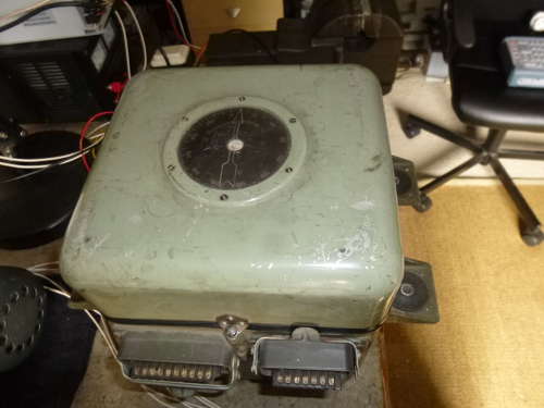
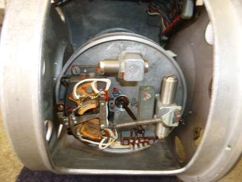
After Patin took over manufacture of the PDS they re-developed the vertical flight gyro design by Anschutz. The unit comprises of the gyro, pendulum and torque motors for vertical alignment in a double gimballed frame. This whole assembly was placed in a Nitrogen filled sealed housing. A separate compartment housed a precession current switch and a computing relay for curve flying.
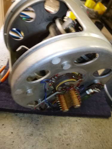
A number of photographs towards the end show the gyro unit removed from its sealed housing. Of particular interest is the pendulums used to measure the aircraft's speed changes. A clever trick that Patin used was to spring load the pendulum in such a way that it becomes unstable around the setpoint. This makes the pendulum far more sensitive to small deviations around the setpoint. Rather than aim to control the pitch, the PDS system merely uses the pitch to control the airspeed of the aircraft; the pendulem gives an indication of the rate of change of the forward speed.
A separate pendulum fitted to the bottom of the gyroscope housing controls torque motors in the gyro gimbals which cause the gyroscope to precess. When the gyro is running very slowly, the torque causes a very quick precession, at full speed however, the torque can only precess the gyro much slower. Furthermore a current saving switch reacts to the amount of current that the gyroscope is drawing and reduces the current to the precession system even furter to about 2 degrees per minute. Should the gyro be knocked out of alignment (if the aircraft is flown at angles exceeding the freedom of movement of the gyro) it would take far to long to re-align the gyro at 2 degrees per minute, so the pilot can initiate a fast alignment process. The gyro is powered by 500 Hz three phase voltage, with phases R,S and T. When fast alignment is initiated, the R and S phases are switched so that the rotary field changes direction. The gyro starts to slow down, stops and runs up again in the opposite direction. This creates a short window of slow running in which the torque motors quickly re-align the gyro with the vertical.
The "Horizonttochter" indicating instrument which provides a readout of the position of the "Horizontmutter". This one needed a major repair (one of the coils had a broken winding), which I am pleased to say succeeded.
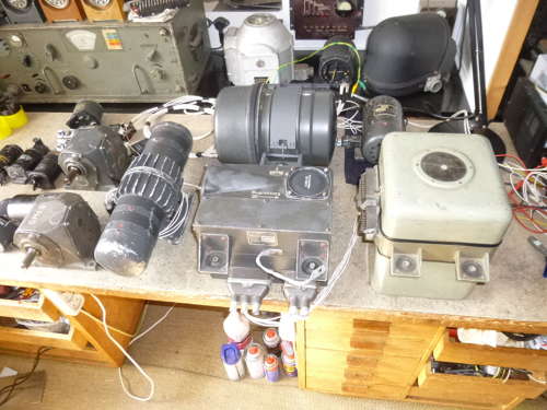
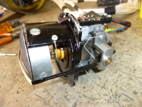
With plenty of time on hand in recent weeks during the Covid-lockdown, I have been working on various other components of the Patin Dreiachsen Steuerung (PDS) autopilot. First I made the missing mounting bracket for the horizontal flight gyro, a complex composite part keeping me busy for well over a week.
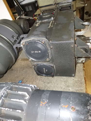
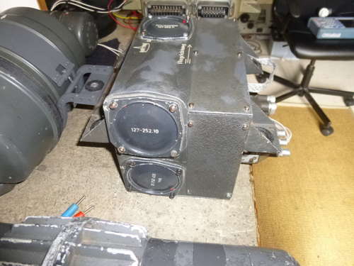
The next component I tackled was the central control unit or "Steuerkasten". I had this in use in a single axle "Kursteuerung" setup, so I exchanged it for the single axle control unit I restored recently and reconfigured it for 3-axle use. This means fitting additional rate gyro units and extra computing relays. Each of these items required some overhaul and calibration. Note that the rate gyro units have a 127-252.1x number; the last digit denotes a different ratio between angular velocity and acceleration output, I managed to restore a 10, 11 and 12 subtype for the yaw, roll and pitch respectively. One of the gyro units had a manufacturing defect (sabotage?) in that the gyro just fouled the housing causing some wild signals! The gyros and relays have been running in and tested for several hours now.
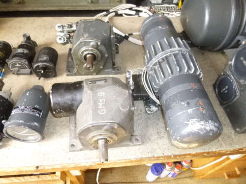
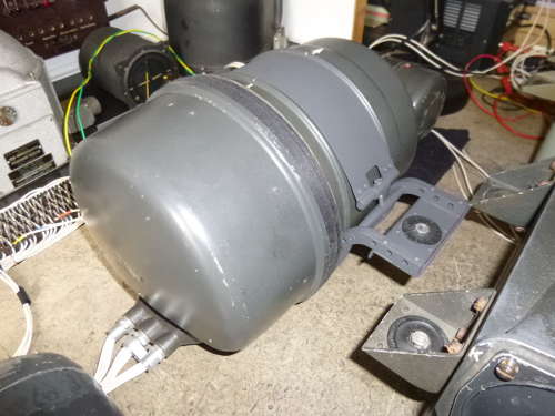
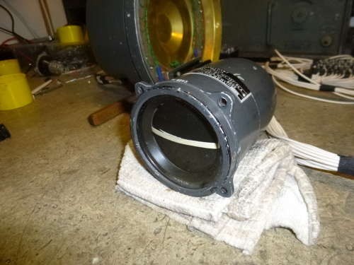
The next on the list was the power drive system. The output signals from the steering box are amplified using a Ward-Leonard system, the rather long rotary converter is the Ward-Leanard generator. This in turn powers the rudder servo motors, two of which can been seen next to the generator. The Ward-Leonard generator had been ripped from an aircraft, with one of the fixing lugs broken off. A new lug was fabricated from some layers of aluminium sheet and epoxy metal and securely attached. I also found that the cooling fan had been removed causing the unit to run hot, so I had to attach a new blower to ensure the unit keeps cool. The bearings and brushes of the Ward-Leanard generator proved to be in perfect condition after 80 years. It highlights that the biggest danger for this equipment is inexpert handling and restoration most revolves around undoing the mess that others have made....
At this point I ran out of wire to build the cabling between the units, so I have not been able to do a loop test linking the various units. New wire is now on order and hopefully I can continue testing later this week.
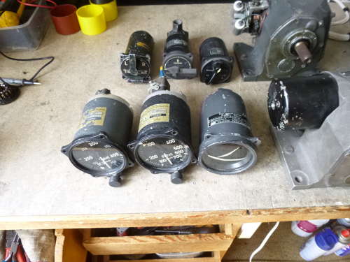
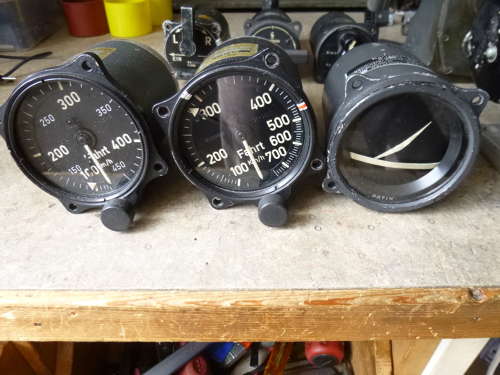
Other photographs show some of the instruments and switchgear associated with the PDS autopilot. Apart from the artificial horizon the system uses a special airspeed indicator with an extra needle for the speed setpoint. Two versions existed, a 450 and a 700 kmh version. The switchgear contain a main switch (off - standby - on) and a bombardiers Left/Right command switch for flying curves. The bombardier would use this switch to adjust the drift angle of the aircraft during the bomb run, this particular switch was used with the Lotfe 7C.
The final unit on the far right is the direction gyro or Patin Kurszentrale (PKZ). This is an auto synchronising gyrocompass which keeps the aircraft pointing towards the set compass direction.
So my first priority is to get more cabling done and looptest the system to make sure all the components are working properly. After that I will have to construct a gimbal system to suspend the vertical flight gyro and the control unit; these two components have to move in unison to replicate the motion of an aircraft so still plenty of challenges ahead!